|
Tip 77 (September 2011)
To CF or Not to CF (cathode follower), that was the question – building a 12B4 zero-gain DAC out to line input buffer stage – J. Noble
Intro by Dick Olsher: Jon Noble returns to these pages with a DIY project that should be of great interest to anyone desperately seeking a fab sounding tube buffer stage. The 12B4 buffer described herein should serve to improve the current drive of not only DAC’s but also highish output impedance phono stages into a typical volume control. While CF’s are typically seen AFTER a volume control, this project provides strong evidence that in some cases a tube buffer can do much good AHEAD of a volume control. CAUTION: DO NOT attempt to build this circuit unless you are an experienced tube circuit builder. Tube circuits, and in particular, HV power supplies, present a risk of serious and even deadly electrical shock. If in doubt, solicit the help of an experienced electronics technician. The author assumes no responsibility for the performance of this circuit.
It may not be correct, but I like to think of this thing as amplifying in reverse – a cathode follower (CF) I mean. I say this because the load is placed in the tail (at the cathode) instead of at the head (or anode) as is the case with a regular gain stage. A CF mostly pulls current to ground and modulates that current in accordance with a signal that comes in on the grid, to put out a more robust (i.e. more current) version of what came in. A CF has some attractive attributes: high input impedance, extremely good headroom at the input, low output impedance, wide bandwidth and very low distortion – thanks largely to 100% localised feedback. The question of whether to use a CF or not to use a CF arose in the context of my Flamingo phono stage mk2, which is almost complete (watch this space). Having seen and liked my circuit, Dick Olsher (DO) asked me if I would build one for him. I was delighted to so but, as it turned out, his needs were a little different than my own. My original plan was to aim for a Zout in the region of 1 to 2K because as much can easily be had from a high current triode gain stage (6H30, 5687 and such like). DO, however, wanted a proper low Zout, in the order of 300 ohms or so, to allow for an effective drive of a wide range of power amplifiers, both solid state and tube alike – he is, after all, an audio reviewer who gets to experiment with a lot of cool gear. A Zout of such value clearly required the use of either a step down transformer or a ‘plane Jane’ CF. I knew I was dead against the use of a CF! Why? Because just about everybody in the DIY community seems to think that CF’s are bad, evil, feedback saturated, fidelity destroying stages. One well-regarded phono designer (Alan Wright) is on record for having called the CF ‘Miss Piggy’, because apparently, she is fat and slow. Well I don’t like slow, and I don’t like fat, and like many others, I had been bad mouthing CF’s around town. Of course I never actually built one, or even tried one in the context of my system! That’s the problem with prejudice – it catches like wild fire, and before long establishes itself as a self-fulfilling prophecy. Email chat with Dick, however, changed all of that and thanks to his confident statement – “I LOVE CF’s, the concept of this stage is both elegant and beautiful” – I was convinced to the give the ol’ CF a try. Boy am I glad I did!
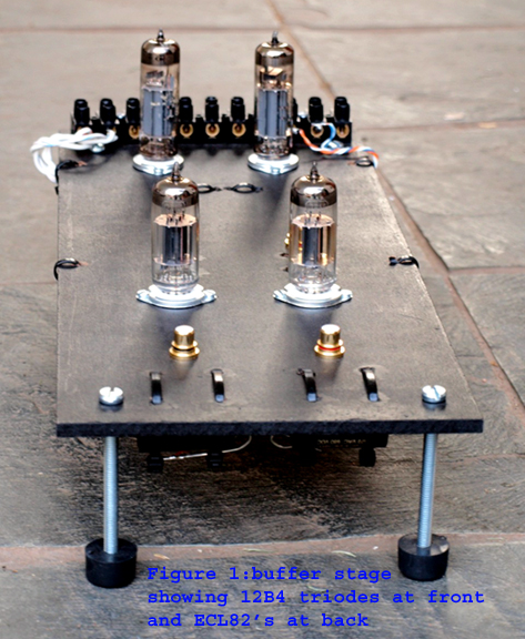
The circuit presented here is a 12B4 triode CF that I recently developed as a buffer stage for my newly acquired Neko Audio D100 mk2 DAC (see figure 1). The D100 DAC is unusual in that it uses a step-up transformer at the output stage – yea that’s right no ‘ringing’ brick wall filters, no op amps, no analogue solid state nothing, no triodes forced into small DAC sized boxes with iffy power supplies and interference from neighbouring digi circuits and compromised coupling caps. Instead, what makes the D100 unique and truly great is the use of top digi tech from Burr Brown and Wolfson fed direct into a pro quality Jensen step up transformer – pure, honest, direct, beautiful. DO had alerted my attention to the D100 and had given his strongest personal recommendation regarding this DAC. Upon reading about this product at the Neko Audio web site I KNEW I WANTED one. The way I see, if a step-up transformer works for my prised moving coil’s in my analogue rig, then why not for top digi chips as the output stage of a DAC!
 |
I got the D100, plugged it in, and was immediately impressed by the grain free, open and sweet nature of its presentation – digi sound with the freedom and soul of analogue. As the DAC began to wear-in, however, it became apparent that the step-up output stage was not entirely happy with driving a 1 meter length of interlink and a 100K volume attenuator at the input to my tube line stage. Some quick experimentation proved that the D100 did not like too much in the way of series resistance, and in my case said 100K attenuator is a ‘shunt style’ attenuator which means a 100K series resistor is always in the path, giving the poor D100 a clear case of an impedance-mismatch-headache. The answer was simple, what I needed was a dedicated buffer stage, one with sufficient headroom to accommodate the fairly high 2 Volt out of a CD player or DAC and one that could sit right alongside (i.e. connected to the DAC via a short 200mm of signal cable) to isolate the D100 from my 1-meter long interlink and 100K attenuator at the input to my line stage. A CF, of sorts, was the obvious choice.
Prior to the D100, I had relied upon my trusty old Marantz CD player. The Marantz has a similar, fulsome and natural tonal balance to that of the D100, and I had had excellent luck from a former 12B4 line stage when used with that digi front end. The 12B4 line stage had won in my system after many former line stage attempts, and contributed to a remarkable sense of energy and dynamic propulsion whilst retaining the fulsome if not ‘gentle’ balance that attracted me to the Marantz in the first place. So with this experience in mind, the 12B4 was an obvious first choice for my buffer attempt. And I have to say I got lucky. It’s not often that one’s first circuit prototype hits the sonic spot, precisely. Miss Piggy hey … I think not!!! This 12B4 CF design is oh so transparent, so direct, honest and true in its portrayal, so fast, dynamic, nuanced and effortless sounding that I am, frankly, frightened to alter it! Listening to the D100, via the 12B4 CF buffer, my 27 line stage, Nelson Pass style F5 power amp and the fantastic BassZilla Platinum mk2 loudspeakers I am getting (on good recordings) a wall to wall and floor to ceiling sound stage with life sized images, depth, inner detail, bass with texture and exceptional fidelity, DYNAMIC resolution, punch, snap and slam, and a host of other things I don’t quite have accepted ‘audiophile’ terms to describe. Simply put, the D100 really comes alive when played with the 12B4 CF as shown in the accompanying circuit diagrams.
Although this 12B4 CF was purpose designed for the D100, I have no doubt it will work with many a DAC or CD player, most of which are not well suited to driving interlink cables and/or challenging input impedances. But note, do not build this circuit if you are looking to add a ‘tubey’ sound, i.e. to add warmth, to obscure digital hardness and such like. This circuit is not intended to colour, to round off raw edges or obscure in any way. The 12B4 CF is simple and very direct at what it does, it passes the message along whilst bringing significant MoJo Dynamic Dynamo, to help bring digi closer to the immersive realism of good analogue sound. If your system, like mine, is already Ying-Yanged for a true and life like tonal balance (by a careful selection of various tube types), then tonal disturbance is not what is required, and in which case the 12B4 CF may just be the right ticket for you.
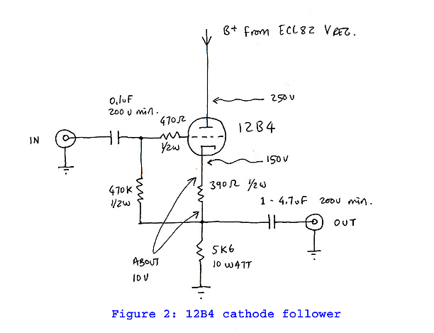
The CF we are considering here is of the ‘boot-strapped’ variety, as already described in the Radiotron Handbook of 1954. This type of CF places a small bias resistor (390 ohm in this case) atop a larger cathode load which connects to ground (5K6), and crucially a grid resistor (470K) ‘boot-straps’ the voltage formed across the bias resister to the triode’s control grid (see figure 2). Merlin Blencowe, the Valve Wizard, calls this type the ‘ac cathode follower’ in contrast to the ‘dc cathode follower’, both of which are beautifully described on his informative web site, see: http://www.freewebs.com/valvewizard/
 |
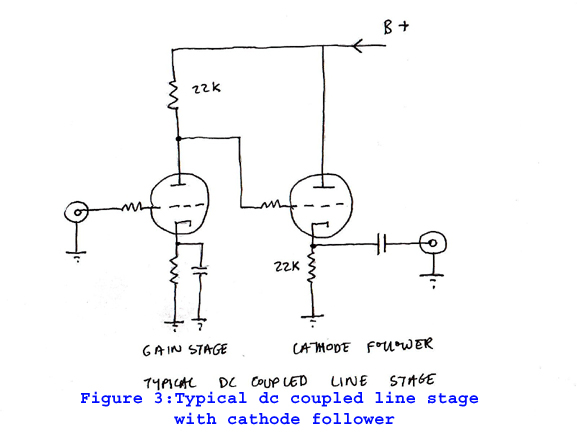
It to common to see audiophile line stages that implement the dc cathode follower, probably because dc coupling the first gain stage to the second CF stage has the advantage of loosing an interstage coupling capacitor (see figure 3). But the problem with this typology is that the bias for the CF is, in effect, provided by a fairly large cathode path resistor, typically in the 10 to 20K region. This resistor will multiply any current instability through the stage and consequently the bias condition for this type of stage won’t be terribly stable under dynamic conditions. DO explained to me that the DC cathode follower is known to bounce up and down, to ‘ring’, and this fact may well be a primary reason for why the CF has received a bum rap (indeed, a stage that rings is likely to sound both fat and slow!). A ‘boot-strapped’ CF requires a further coupling cap at its input but does not suffer bias instability – thanks to the book-strap this type of CF looks to be every bit as stable as a regular cathode biased gain stage. Some say a constant current source helps to enhances the stability of a CF, and I do intend to explore this option for the near future, and promise to add an update should I feel this is worth implementing in the context of this design (but somehow, I don’t think a CCS is required in this case).
 |
A further issue that should be addressed with a CF is poor rejection of power supply ripple. With a regular gain stage the load that sits on the anode helps to protect the triode from power supply anomalies, whereas with a CF the anode connects directly to the high voltage supply and is therefore very much exposed. One way to address this problem is to use a pentode for the CF, because the ‘flat’ load lines of a pentode will help a fair bit in this context. But the approach I have chosen for my design is to regulate the power supply, i.e. to kill B+ fluctuations at source. The power supply regulator that I have selected for this project is a ‘single tube’, series pass voltage regulator designed by Mike Vans Evers , and you can read about his elegant design here (see figure 4): http://www.enjoythemusic.com/magazine/sound_practices/3/one_tube_regulator.htm
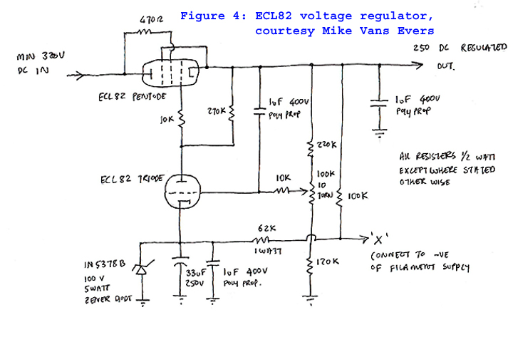 |
I have to say that I built Mike’s ECL82 Vreg some time back and feel deeply, madly in LOVE! The ECL82 combines an almost EL84 pentode and a 12AX7 like triode in a single bottle, and as many of you will know, the EL84 is one sweeeeeeeeeet sounding pentode (I’d say one of the very best!). Since ECL82’s are not commonly used these days, quality vintage old stock can be had at very reasonable prices, which is super nice! I am currently using a NOS pair of Telefunken ECL82, and have a further NOS pair of Valvo’s to space, all of which sound truly SUPERB in this circuit. The question of passive versus regulated supplies is an interesting one for me, and all I wish to say is that after years of building purely passive supplies a GOOD series pass regulator is certainly NOT the sonic evil that some claim it to be (i.e. evil due to pentode with feedback in series with the supply, no less!). The main issue I have with passive supplies is that sound is hugely dependent upon the value and type of smoothing capacitors used (read ‘cap colorations’!!!), and yes I have tried all the regular contenders, poly prop, paper in oil, poly prop in oil, Black Gates and so on. I never met a completely ‘honest’ sounding power supply capacitor, as all seem to come with ‘issues’ – Black Gates included. What I love about this simple ECL voltage reg is the true and highly refined nature of the sound, which would appear to be largely devoid of supply induced colorations – the quiet nature of the supply, it’s tremendous inner detail and bass slam are further ‘yummy’ aspects to have!
Study of the formulae provided at Merlin’s site demonstrate that a CF, in effect, pits gain (mu) against plate impedance (Rp), to lower signal impedance at the output of the stage. A pentode CF will typically, for instance, use a lot of gain to lower an already very high internal impedance, to arrive back at a low signal Z out (which feels like a lot of hard work to me!). My intention for this design was precisely the opposite – to select a high current triode with low plate resistance, such that low amounts of gain would be adequate for an even lower signal Z out. I’m of the opinion that – all things being equal (which rarely is the case) – low mu triodes sound best and hence this approach has strong appeal for me. The 12B4 is an excellent candidate for achieving this intention. Biased as it is here, at about 10 volts for a quiescent current of around 25mA, the 12B4 pulls lots of current to ground, indeed far more that the signal current amplified, and is likely therefore to be very stable under dynamic signal conditions. Plate dissipation at this operating point (roughly 100V and 25mA) calculates at 2.5 Watt, which is well below the 5.5 Watt maximum rating for the 12B4 – this baby is one tough little ‘power’ triode! We could bias the stage for more current but the ECL82 Vreg can only supply up to 35mA, and at 25mA we are within 75% of that maximum condition. Biasing at 25 milliamps means that all tube stages are assured a decent longevity. Clearly, dual ECL82 regulators (i.e. one per channel) are required.
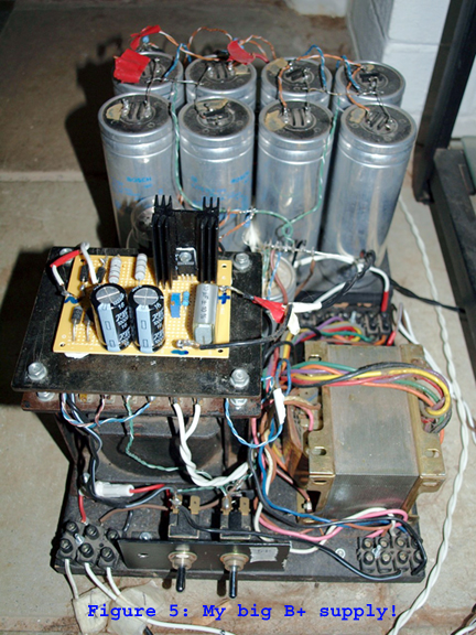
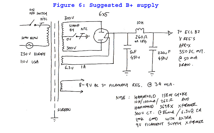
The circuit will bias up correctly with 250V dc to the 12B4’s plate, and that voltage may be dialed in by adjusting the 10 turn pots to each of the dual regulator circuits (the test voltages shown on the diagram are approximate, for example the cathode can easily sit anywhere from say 140 to 160V, and the bias anywhere from 9 to 11V as measured across the 390 Ohm resistor). The EL82 pentode itself needs to drop a minimum of 70V in order to regulate, which means the regulator must be supplied with a dc supply voltage of 320V or higher. The dc supply can be built any which way you prefer, but obviously must be capable of supplying, at minimum, 50mA of current at 320V dc. The supply I am using is quite a monster (I like BIG supplies), built from an old Leak power transformer (with at least 200mA of B+ capability), a separate filament supply transformer, a lovely 83 mercury vapour rectifier followed by an LCLC filtered supply which puts out a solid 550 volt DC (see figure 5 – the large alu can caps you see there are metalized paper in oil types, but which are not connected at the present time). This supply is somewhat over the top, but bare in mind I also use this supply to power my Blue Velvet bass line stage (for bi-amping my BassZilla) which now has its own dedicated ECL82 regulators. I should think an 80mA at 330VDC capable power supply, with your preferred tube rectifier and CLC filtering (lets say 5uF/5 to 10H/220uF) is all that would be required for lovely results – and regular electrolytic caps are completely fine in this context (thanks to the fabulous ECL82 Vreg!). I am including an example of said supply that should work well, one that I calculated using PSU Designer2 which normally provides a decent and reliable simulation, but please note that I have not built and tested this supply (see figure 6). Voltage out can usually be raised by increasing the first cap (5uF), should this be required.
 |
 |
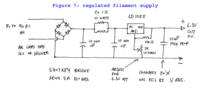
Filaments for the two 12B4’s and ECL82’s can all be wired in parallel and powered by a single filament supply. This supply must be floated at around 155v by connecting the negative side of the filament to point ‘x’ that is indicated on the Vreg diagram (see figure 4) – point ‘x’ being the centre point of a voltage divider (100K and 62K), and note that only one voltage divider is required for the single filament supply, which in turn means it (the voltage divider) may be built on either one of the ECL82 Vregs, it does not matter which. You can build this project with an ac filament supply. I did as much, and it plays perfectly well without any audible noise, however, sound is greatly improved by adding a regulated filament supply (more focus, better timing, better extension and inner detail, etc.), which can effectively be achieved from a single LD1085 regulator chip (see figure 7). To repeat point ‘x’, on one of the ECL82 Vregs, should be connected to the negative side of this regulated filament supply. Be sure to use a generous 5.5 deg C/W heatsink with free flowing air all around, as this little LD1085 chip has to supply a full 2.8 amps at 6.3v (i.e. that’s one seriously hot little chip). You can build this entire shebang on a 90 x 70 mm spot board (or vero board), and normally I just hard wire these babies at the bottom of the board as I can’t be bothered with developing printed circuit boards.
 |
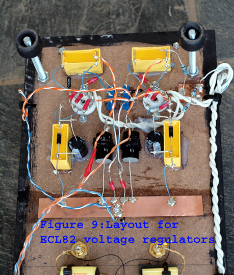
The ECL82 Vreg can be built with bog standard parts, such as generic ½ watt metal film resisters, AC ‘suppressor’ type 1uF poly prop caps (these are rated to accommodate 230VAC, i.e. can handle at least 460VDC), and a regular 33uF electrolytic bypass cap to the zener voltage reference diode. I have built this regulator like this and it sounds absolutely great! In the final build, however, I went for some boutique resistors (mostly PRP and Holco’s), as well Solen 1uF caps at the output stage (from + to ground), and am not yet sure if the extra expense was justified (figure 8 shows the layout below deck, figure 9 zooms in to show how I laid out the Vreg circuit). The CF circuit, however, should be built from good quality parts, and I would firmly recommend a Mills 10 watt wire wound for the main 5K6 cathode resister load, whilst all other resisters could be of Holco, Takman or PRP metal film ilk (figure 10 zooms in to shows how I laid out the CF circuit). The 0.1uF input couple cap I am using at present is a RelCap PCU, polyprop and copper foil type (a fantastic signal cap, btw) which is 200 volt rated (200V is adequate for here) – although I can see myself replacing this with a RelCap Teflon and tin foil type in months to come. The best choice of output cap is Mundorf (from a performance to cost ratio point of view), a Supreme, or if your prefer silver/oil, or even a silver/gold/oil will likely be great here. At present I am using a 1uF Mundorf Supreme bypassed with a 10nF Mundorf silver in oil that I happened to have to hand. And note that the size of this output cap can be anything from 1 to 4.7uF depending upon the load you intend to drive – 1uF is good for a 100K load, and 4.7uF for a load as low as 10K.
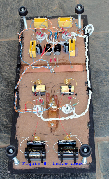 The photographs (figures 1, 8, 9 and 10) also show my latest method of construction, based around 6mm thick MDF, which is intended to be light and non-resonant and also allows for easy of access because I hate wiring-up inside a restrictive box. What you see here is just the ‘carcass’ to which a cosmetic facia/top may be added – but since this particular unit is destined to sit on a low level shelf, almost out of sight, I am likely to leave as is. I guess that’s about it except to say please do let me know if you should build this circuit, or something derived from it, as comments from others are always appreciated! The photographs (figures 1, 8, 9 and 10) also show my latest method of construction, based around 6mm thick MDF, which is intended to be light and non-resonant and also allows for easy of access because I hate wiring-up inside a restrictive box. What you see here is just the ‘carcass’ to which a cosmetic facia/top may be added – but since this particular unit is destined to sit on a low level shelf, almost out of sight, I am likely to leave as is. I guess that’s about it except to say please do let me know if you should build this circuit, or something derived from it, as comments from others are always appreciated!
|